
Alcohol Interlock Installation Guidance Document
Vehicle type : GX42D
1. System Electrical Principle
The below figure show the working principle of the alcohol interlock.When the breathalyzer test is not performed or the breathalyzer test fails, the alcohol interlock control unit will remain in a NOT READY state. In this case, the start signal between the ingnition switch and the start control signal will be disconnected, preventing the vehicle from entering the READY state.The Start signal communication between the ingnition switch and the start control signal is connected only when the alcohol interlock detects that the alcohol concentration is below the set limit (20mg/100ml, the detection limit varies in different countries and regions). At this time, the driver brakes and press the button start,then the vehicle can ready and shift normally. This principle complies with requirement 3a in Annex C of EN 50436-7:2016.
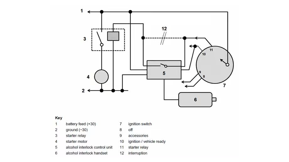
Figure 1. Functional Schematic Diagram
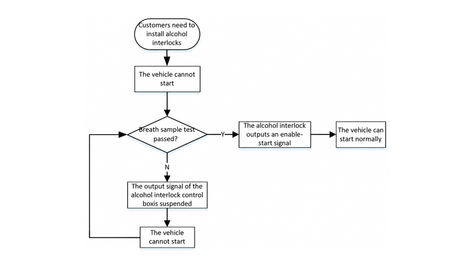
Figure 2. Logic Block Diagram
2. Electrical shielding definition
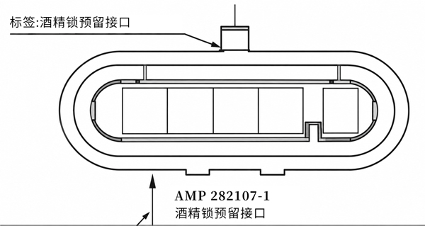
A dedicated reserved interface for installing the alcohol interlock device is provided inside the co-driver’s third-layer dashboard. For fuel-powered vehicles, a five-pin connector is reserved; for electric vehicles, a five-pin connector and a two-pin connector are reserved. Connector definitions are as follows:
| Table 1 Vehicle reserved connector definition(five-pin) | ||||
| Connector type and figure | Terminal assignment | Cable cross section | Corresponding insurance size | Function definition |
 | 1 | 0.75mm2 | / | Start signal output ( to vehicle ) |
| 2 | 0.75mm2 | / | Start signal input ( from ingnition switch ) | |
| 3 | 0.75mm2 | 5A ( share fuse) | Wake-up signal(Terminal 15) | |
| 4 | 1.5 mm2 | / | Ground for power supply | |
| 5 | 1.0mm2 | 10A | Positive power supply | |
5-pin connector model: AMP 282107-1 (mating connector model: AMP 282089-1).
The functions of the five-hole connector are defined as follows:
| NO. | Connector functions defined |
| Hole site 1 | Vehicle START signal output, to vehicle |
| Hole site 2 | Vehicle START signal input, from ingnition switch |
| Hole site 3 | Wake-up signal for alcohol interlock controller, from KL15 power supply |
| Hole site 4 | Ground wire |
| Hole site 5 | Power supply for alcohol interlock controller, from positive terminal of battery |
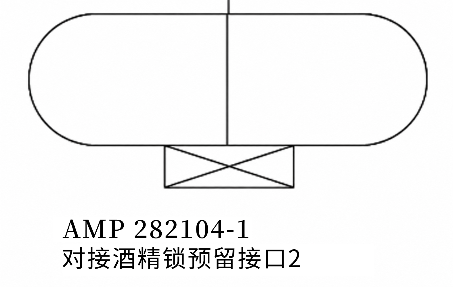
For electric vehicles,there is also a two-pin connector; the connector definitions are as follows:
| Table 2 Vehicle reserved connector definition(two-pin_For electric vehicles) | ||||
|---|---|---|---|---|
| Connector type and figure | Terminal assignment | Cable cross section | Corresponding insurance size | Function definition |
 | 1 | / | / | / |
| 2 | 0.75mm2 | / | Vehicle start feedback signal | |
2-pin connector model: AMP 282104-1; mating connector model: AMP 282080-1.
The functions of the five-hole connector are defined as follows:
| NO. | Connector functions defined |
| Hole site 1 | / |
| Hole site 2 | When the vehicle’s high-voltage system is activated, a continuous 24V electrical signal is output. |
3.Hardware installation instructions
Installation only can be carried out by Professional technicians with expertise in vehicle electronic systems and knowledge of relevant special installation requirements according to the respective assembly instructions. When choosing the installation site, the existing regulations for the interior of vehicles have to be observed.
| Installation steps for alcohol interlocks | |
|---|---|
| Step 1 | Power off the vehicle and turn off the main power. |
| Step 2 | Remove the front passenger interior trim panel, taking care to protect the interior during disassembly to avoid damage or scratches.and locate the connector pre-installed inside the third-layer board. |
| Step 3 | 1. Remove the mating connector from the reserved interface.Crimp or solder the terminals/wiring from the connector to the corresponding wiring harness of the alcohol lock device to ensure a secure, non-detachable connection. After crimping or soldering, insulate the joint with electrical tape or heat-shrink tubing (or hot-melt adhesive), ensuring full dielectric protection. Alternatively, direct mating with a compatible connector type may be performed, depending on the on-site installation requirements. 2. After all cable connections are completed and insulation resistance testing is passed, proceed to install the control box; secure it to the vehicle using hook-and-loop (Velcro) straps or cable ties, mounting it in a suitable available space within the vehicle cabin |
| Step 4 | 1. According to customer requirements, mount the handset holder at a location easily accessible to the driver, ensuring no obstruction of any vehicle control components. The holder may be secured to the instrument panel using hook-and-loop (Velcro) straps or screws. If mounting with screws, install the holder only on flat, structurally sound surfaces, and take care to avoid damaging interior trim during installation. 2. Insert one end of the handset cable into the control box and the other end into the handset; then place the handset into its holder |
| Step 5 | 1. After installation is completed, reinstall the interior trim panel, ensuring all cables are securely fastened—without impeding the driver or passengers—and confirming there is no cable interference 2. Reconnect the low-voltage battery. Verify that the handheld device powers on and operates normally. Attempt to start the vehicle: if the alcohol test has not been completed or the result is unpassed, the vehicle must not start; only after a successfully completed and passed alcohol test should the vehicle start normally—confirming that the installation meets acceptance criteria. |
4.Safety hazards and considerations during installation
4.1 Do not install holster for the handset in front of air-bags.
4.2 Ensure that all control unit cables, as well as newly established electrical connections to the vehicle, are firmly attached and are not exposed to any tensile stress following installation. recommend bundling the control unit cables, e.g. with duct tape, to ensure they do not hang loose and thus preventing any manipulation.
4.3 Control box mounting location: The control box shall be securely mounted at an appropriate location inside the driver’s cabin, and must not loosen or interfere with driving experience or vehicle operational safety.
4.4 Handheld device mounting location: The handheld device may be placed at a convenient location accessible to the driver; alternatively, it may be secured to the instrument panel using hook-and-loop fastener straps or screws. Installation is strictly prohibited within the steering wheel area or the airbag deployment zone.
5.Other explanation
5.1 To deactivate the alcohol lock device, it must be removed by qualified professionals: the component shall be physically removed, the interior trim restored to its original condition, and the reserved 5-pin connector must be mated with a dedicated OEM-compatible mating connector—ensuring normal vehicle startup.
5.2 Alcohol interlock system use reference——The OEM vehicle only reserves generic interfaces; the specific operation logic and HMI display of the alcohol interlock device are determined solely by the aftermarket alcohol interlock product.
User Manual:
Step 1 : The alcohol interlock system should be activated after the vehicle is powered ON,
Step 2 : Providing a breath sample,Blow evenly into the mouthpiece as long as a continuous tone sounds.
Step 3 : If the measured breath alcohol concentration is below the set limit value.Test passed is displayed.The vehicle is cleared to start.
Step 4 : If the measured breath alcohol concentration is above the set limit value. The vehicle cannot start.
The installed alcohol interlock can only in allowing the vehicle to move under its own power upon the activation of the vehicle master control switch and the alcohol interlock can not influence a moving vehicle